Blender -> Realm Builder
Exporting custom modules design from Blender to Realm Builder
In addition to the procedures outlined in the Blender -> Godot section for exporting/importing static meshes, modules for the Realm Builder should satisfy additional requirements.
Blender
Module position
The pivot point determines the origin of the module within the grid system.
The base of the first
Occupied cell/Module Area Cellis at the coordinates 0,0,0 and centred on the pivot point.No part of the mesh should be located below the pivot point (-Z Axis in Blender/-Y Axis in Godot).
If the module is designed to fit seamlessly against another module, it can be useful to create a wireframe mesh of the two grid systems in Blender since cells cannot be occupied by two modules of the same module class.
Prior to exporting the module place the chosen pivot point location of the module at the origin of the Blender coordinate system origin (0,0,0), select the mesh and choose
Object->Apply->All Transforms
Materials
In addition to the requirements for Static Meshes - Materials Realm Builder offers the feature to change materials on the fly. To enable this feature create a new placeholder material and name it
base_module_colourordecoration_module_colour.
Object naming
In addition to using the object name suffix
-color-colonlyto define collision meshes in Blender it is also recommended to incorporate a designation for the module type:B- Base moduleSB- Side base moduleCB- Corner base moduleSMB- Semi base moduleD- Decoration moduleSD- Side decoration moduleCD- Corner decoration module
Additional designations to further define the object for example
G_Cube_D_1-colbased onCategoryName_ModuleName_ModuleType_VariationNumber-CollisionTypeare recommended.In Blender multiple objects can be renamed simoultaneously by selecting the meshes and
Edit->Batch Rename...
Vertex Count
As a rough guide the vertex count for base modules should not exceed 10.000 vertices per 4x4m cell.
The appearance of smooth and rounded surfaces can still be achieved with faceted surfaces by selecting the object in Blender and
RMB->Shade Smooth. In this caseObject Properties->Object Data Properties->Normals->Auto Smoothshould be enabled and the smoothing angle specified.
Modular Design
We encourage all builders to incorporate the modular approach into their asset design. Instead of joining the meshes of entire scenes and exporting them as a single module try t
Godot
Node setup - Basic
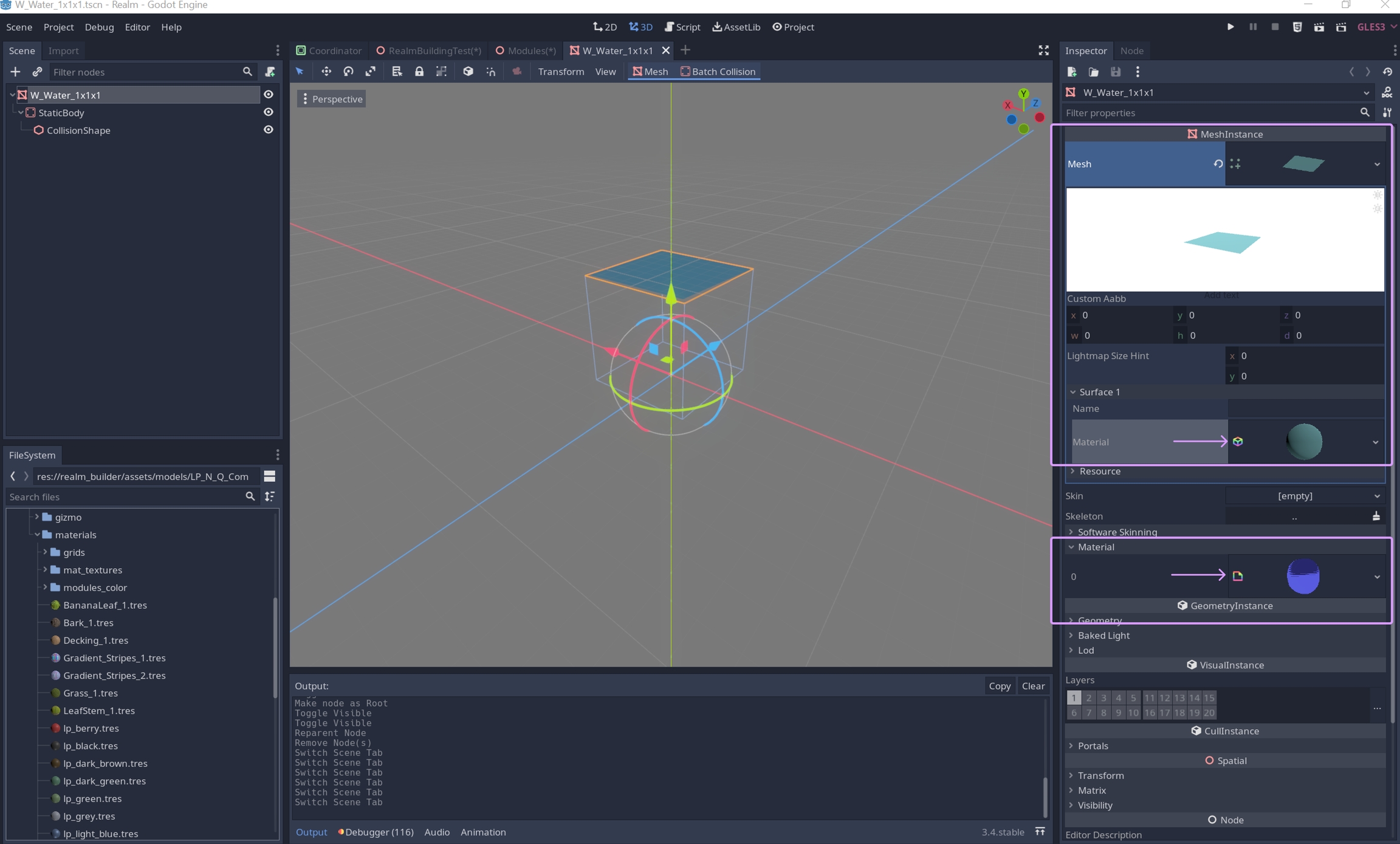
In addition to to the import procedure described in Static Meshes ensure that the mesh instance is set as the root node with
RMB->Make Scene Root.If the collision mesh came as a separate mesh from Blender using
-colonlyplace thestatic bodynode directly under the root node.Delete any other remaining nodes.
Materials
For each mesh instance there are two locations where materials can be assigned.
The first one is in the
Inspectorpanel underMesh->Surface. This location should only have spatial materials assigned to it for example.tresfiles. Any other type of shader assigned to the mesh in this location will crash the builder upon placing the module.The second location is also in the
Inspectorpanel underMaterial. Any shader assigned to the mesh in this location will override the shader in the first location.
The following section is predominantly for internal use, however it might be useful for community builders to understand the entire process. In addition we are working towards fully automating these procedures to streamline the import/export pipeline and empower our community builders to fully test their creations as quicky as possible.
Update Resources
Drag and drop new MODULE_NAME.tscn file into the
Modules.tscnnode tree.Scene->Convert To...->MeshLibraryto update existing mesh libraryIf modules were added to a specific location in the node tree or others deleted/rearranged then during saving delete the existing
realm_builder_modules.meshliband save the new one using the same name. Openrealm_builder_modules.tresand drag and droprealm_builder_modules.meshlibinto the corresponding slot in the inspector.Open
realm_builder_modules.tresand clickUpdatein theInspectorpanel andSave.
Cell Evaluation
The Realm Builder is based on Godot's Gridmaps tool. In order to correctly place, select, rotate or move a module we need to define the Module Area Cells and Occupied Cells. Both evaluations are executed within CellEvaluation.tscn .
Both evaluations are executed within
CellEvaluation.tscn.For regular non-overlapping modules with collisions the
Module Area CellsandOccupied Cellsare the same.Overlapping modules require a
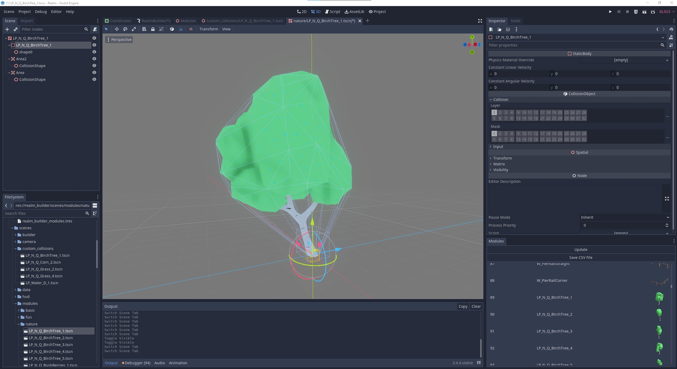
Custom Evaluationto define the occupied cells.Modules without in-game collisions require a
Custom collision scenewhich is assigned to the respective module inrealm_builder_modules.tres. It enables object selection inside the builder tool but does not collide with the player during play mode.NOTE: During the cell evaluation process
ConcavePolygonShapesare regarded as hollow, whereas primitive shapes such asBoxShapesandConvexPolygonShapesare regarded as solid. That means if a cell is fully enclosed by aConcavePolygonShape, it will not register during the scan. Therefore a supplemental area node with a primitive shape must be added to any fully enclosed cell or if possible aConvexPolygonShapeby selecting the source mesh andBatch Collision->Create Convex Static Body.NOTE: Any module must have an
Occupied Celland aModule Area Cellassigned at its pivot/origin. Furthermore no cell value should be negative. Therefore the pivot position must be taken into account prior to exporting a modules to Godot. These are the most common reasons for modules to not function properly.
| Module Instance | Evaluation Type |
|---|---|
A. Collision + Non-overlapping | Standard Cell Evaluation |
B. Collision + Overlapping | Custom Cell Evaluation |
C. No Collision + Non-overlapping | Standard Cell Evaluation + |
D. No Collision + Overlapping | Custom Cell Evaluation + |
E. Partial Collision + Overlapping | Custom Cell Evaluation + |
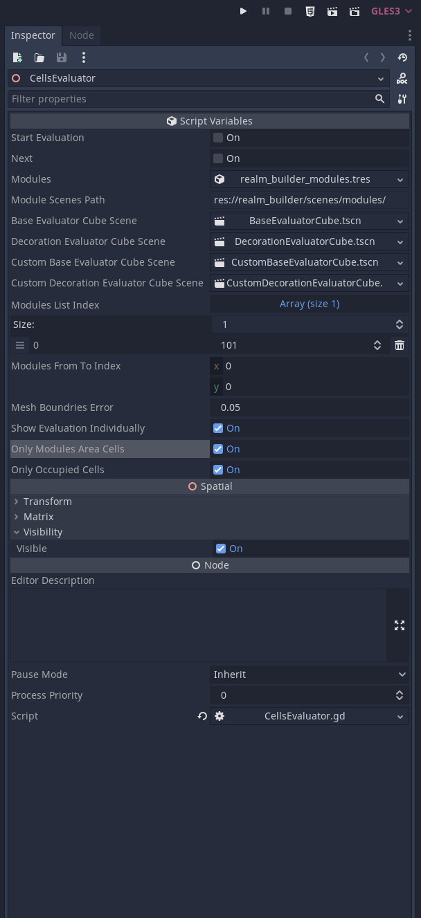
DO NOT TOGGLE
Start Evaluation!!! Always ensure that a specific evaluation range has been specified beforehand inModules List IndexorModules From To Index. Otherwise the evaluation will cycle through the entire meshlibrary and will also overwrite any values which have been edited manually which cannot be undone inside of Godot. Howeverrealm_builder_modules.treswhich stores the values for occupied cells can be reset in your git client.
Module Area Cells
Module Area Cellsare essential for selecting modules inside the builder tool. Only areas of a collision mesh with aModule Area Cellassigned to them are selectable.When a user points and clicks on a collision mesh, that particular point in the coordinate system is referenced against all the modules which have a
Module Area Cellcurrently occupying that location.If multiple modules are present in the same location then the more recently placed module will be selected (WIP).
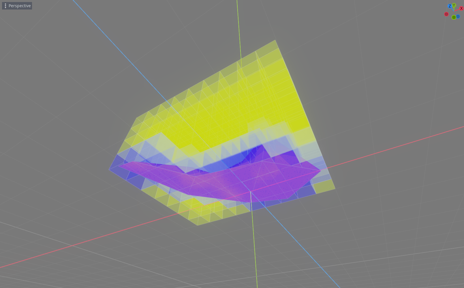
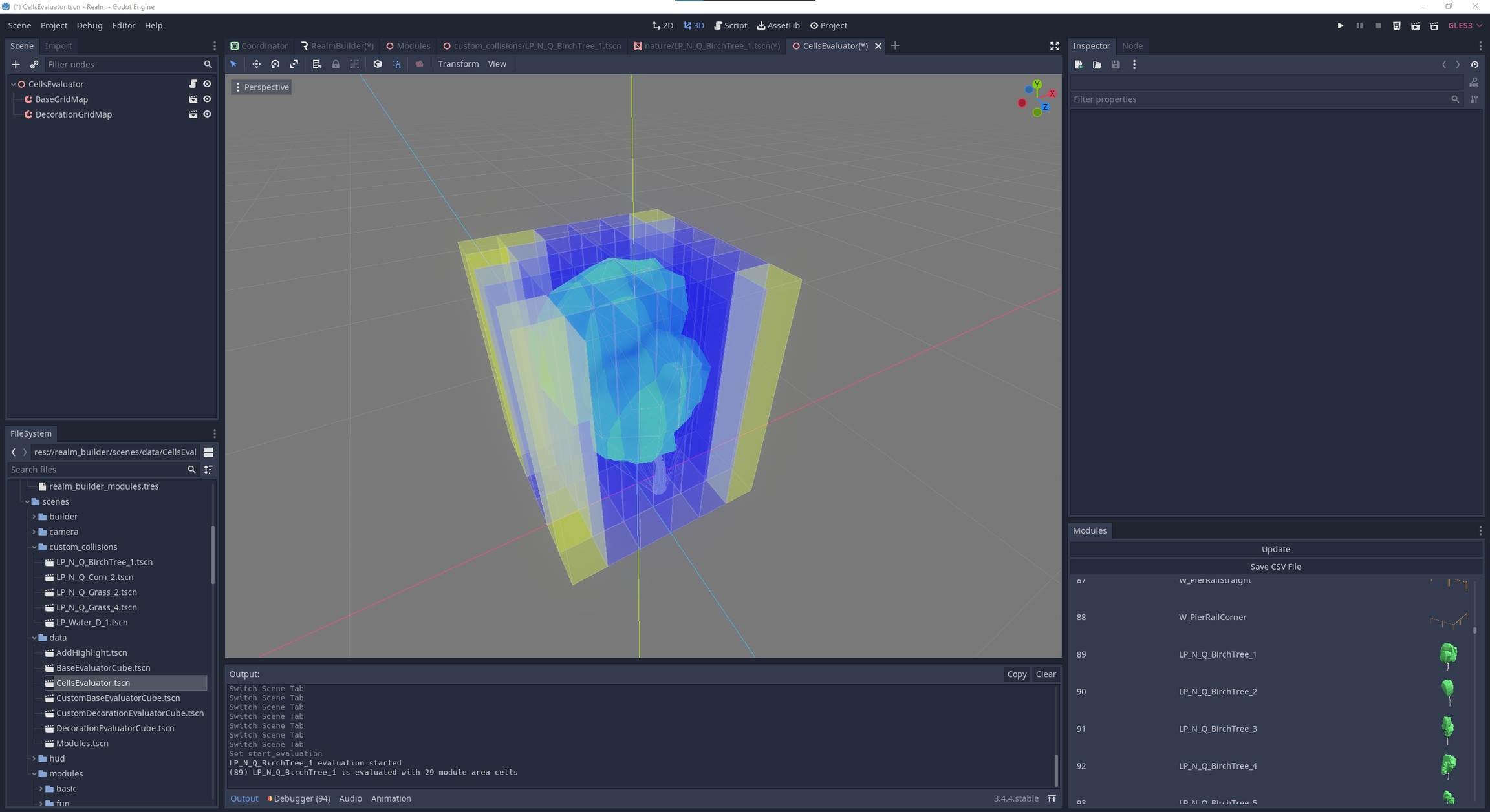
With
Show Evaluation Individuallyenabled in theCellEvaluation.tscninspector the scan will be visually represented inside the editor. This is a useful feature, especially for larger modules and to check that the entire mesh surface is covered. Yellow cells represent an assigned cell and the blue cells an unassigned cell.CellEvaluation.tscnscans forModule Area Cellsby detectingCollisionShapeson collision layer 1. If anAreanode is used to manually place aCollisionShapeyou cannot use aConcavePolygonShapebut should use primitive shapes like theBoxShape,CylinderShape...
| Evaluated Nodes | Properties |
|---|---|
| Collision Layer 1 - default (in-game collision) |
|
|
| Collision Layer 1 - default (NO in-game collision) |
|
|
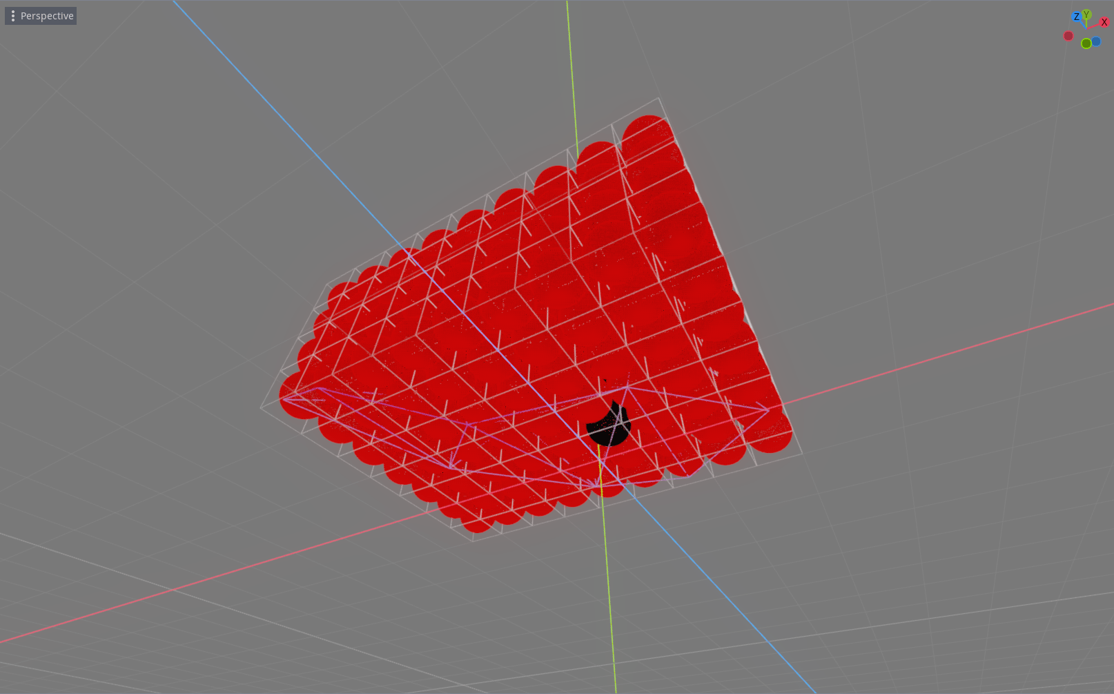
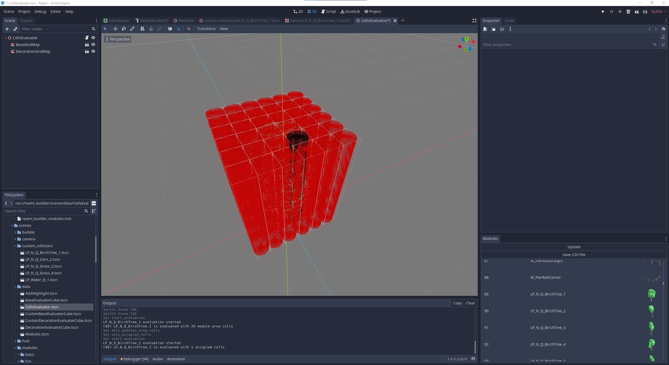
Occupied Cells
Everytime a module is placed it must occupy at least one cell of the Gridmap and only one module can occupy that cell on the Gridmap at a time.
Cells of different Gridmaps can overlap, therefore a base module (4x4x4m grid) and a decoration module (1x1x1m grid) can be present at the same location in the coordinate sytem.
CellEvaluation.tscnscans forOccupiedCellsby detectingCollisionShapeson collision layer 1 or collision layer 4 (custom evaluation). If anAreanode is used to manually place aCollisionShapeyou cannot use aConcavePolygonShapebut should use primitive shapes like theBoxShape,CylinderShape...
| Evaluated Nodes | Properties |
|---|---|
| Collision Layer 1 - default (in-game collision) |
|
|
| Collision Layer 1 - default (NO in-game collision) |
|
|
or for Custom Evaluation | |
| Collision Layer 4 - occupied_cells_only (NO in-game collision) |
|
|
Node Setup - Advanced
A. Collision + Non-overlapping
| Module Nodes | Properties |
|---|---|
| |
| Collision Layer 1 - |
|
|
( | Collision Layer 1 - |
|
|
B. Collision + Overlapping
| Module Nodes | Properties |
|---|---|
| |
| Collision Layer 1 - |
|
|
( | Collision Layer 1 - |
|
|
| Layer 4 - |
|
|
Enable
Custom Evalutioninrealm_builder_modules.tresinspectorOpen
CellsEvaluator.tscn, specify range, start evaluation
C. No Collision +Non-overlapping
| Module Nodes | Properties |
|---|---|
| |
| Collision Layer 1 - |
|
|
| Custom Collision Nodes | Properties |
|---|---|
| |
| Collision Layer 5 - |
|
|
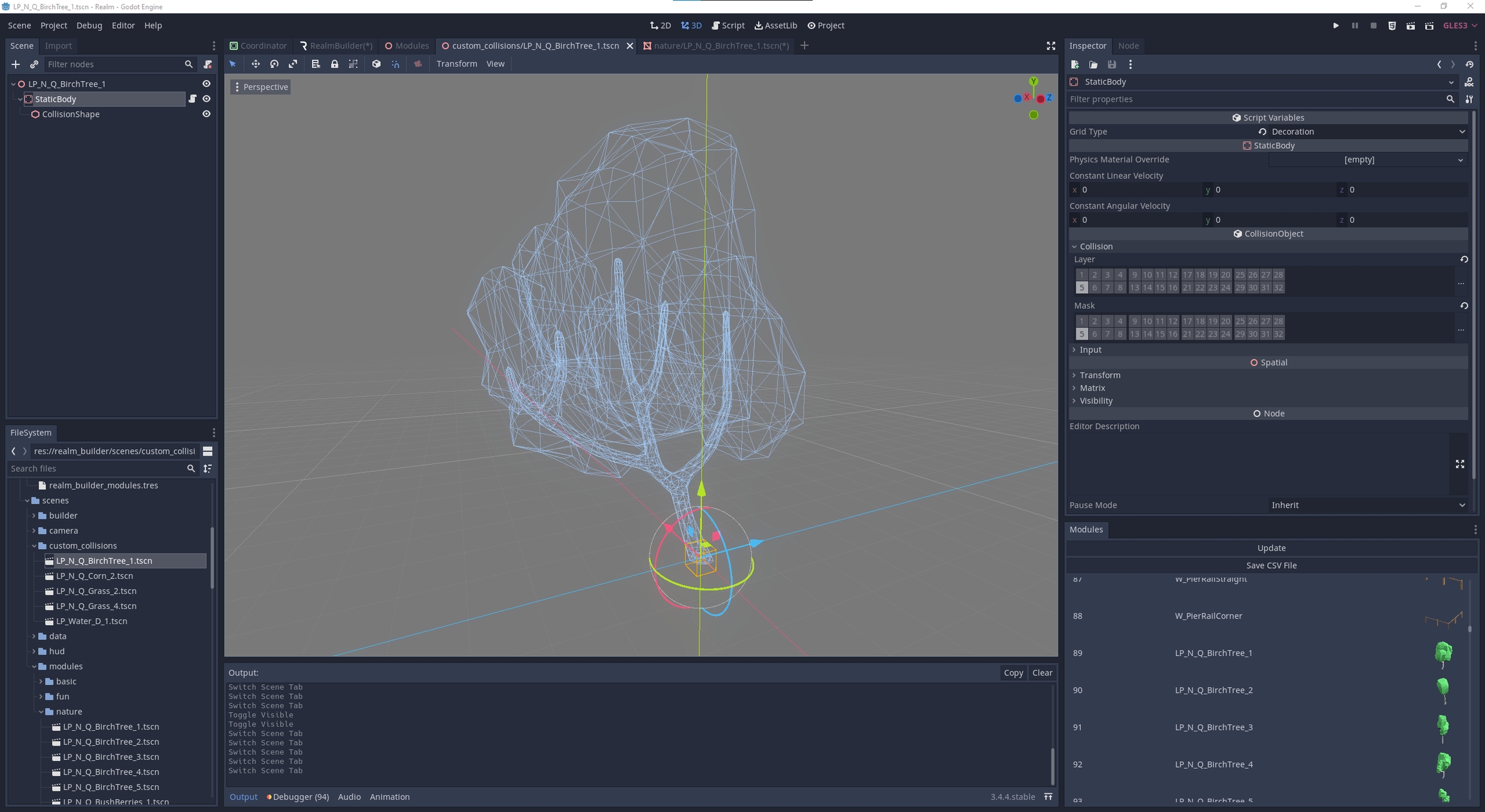
Rename
Spatialto [MeshInstance_NAME]Attach (DragDrop)
CustomCollisionController.gdontoStaticBodySet
Grid TypeinInspectorunderScript VariablesAttach (DragDrop) custom collision scene to module in
realm_builder_modules.tresOpen
CellsEvaluator.tscn, specify range, start evaluation
D. No Collision + Overlapping
| Module Nodes | Properties |
|---|---|
| |
| Collision Layer 1 - |
|
|
| Layer 4 - |
|
|
| Custom Collision Nodes | Properties |
|---|---|
| Same name as source |
| Collision Layer 5 - |
|
|
Rename
Spatialto [MeshInstance_NAME]Attach (DragDrop)
CustomCollisionController.gdontoStaticBodySet
Grid TypeinInspectorunderScript VariablesAttach (DragDrop) custom collision scene to module in
realm_builder_modules.tresEnable
Custom Evalutioninrealm_builder_modules.tresInspectorOpen
CellsEvaluator.tscn, specify range, start evaluation
E. Partial Collision + Overlapping
| Module Nodes | Properties |
|---|---|
| |
| Collision Layer 1 - |
|
|
| Collision Layer 1 - |
|
|
| Layer 4 - |
|
|
| Custom Collision Nodes | Properties |
|---|---|
| |
| Collision Layer 5 - |
|
|
Last updated